AKP 27/11/2012
Slenderness of structures
Fundamental: engineers use the word “Buckling” far too often (you might find this comment repeated elsewhere just a few times) since structures are usually designed to be robust when acting as a long member. This means that they might start to go non-linear (whenever you see the terms slenderness or effective length being used then you are getting into that territory) but they are usually going to reach yield long before they buckle. Buckling is in fact a purely elastic state and does not take account of yield strength.
Slenderness of an element gives a measure of the load at which a section will yield locally, compared to the load at which the element will buckle. You will understand slenderness at a gut level, without necessarily realising what it actually leads to. Struts are the easiest form to understand, so I will discuss them here, but beams show similar behaviour under bending. If your strut can go into full compressive yield at any section along its length and not come close to global buckling, then it is stocky and you can really load it up. If, however, the structure is long and whippy (don’t you just love the nice precise terms) then the strut will buckle as a body long before it can reach yield and you cannot rely on it to take much load at all. But slenderness is related to the behaviour of an element, like a strut, acting as a whole body: later on, I will discuss compactness, which is a measure of how much stress you can put on a local cross section before it buckles locally.
Fundamental: slenderness is large scale, compactness is local scale.
The various documents in a set of codes are usually interdependent. It is very important not to mix and match clauses between different sets of codes because we do not usually know enough about the background to understand how they all fit together.
An example is the behaviour of slender beams and struts in BS5400, although this actually applies, with variations, to the other code sets as well. BS5400 Part 6 is often overlooked by design engineers: it is the workmanship part of the code and most engineers initially think that it only applies to work during construction. But there are calculations in Part 3 (steelwork design) which rely directly on the quality of work allowed in Part 6. Absolute straightness of any metal part can be approached but can never be guaranteed, and that is before you start doing nasty things like melting small areas of the steel and allowing it to cool down in uncontrolled conditions (you might know this as welding) which tends to cause permanent deformations.
Part 6 includes acceptable tolerances on criteria like straightness, and a typical limit is that the maximum transverse offset of a beam top flange at midspan is length/1000.What that mouthful means is that a 50m long beam can deviate up to 50mm away from a straight line joining the ends. I do not know what value is used in the design code, but if you are doing non-linear analysis the Network Rail assessment code requires an additional 20% lack of straightness. Most engineers then assume that the beam follows a nice neat parabola (or two or three if they are looking at multiple waves of imperfection).
So where does this imperfection come into play? I have carried out more non-linear analyses on trusses than I have on beams, and there are fewer outside influences that come into play, so I will discuss the behaviour of the top chord of a truss as a compression strut, although hopefully you will not have to think too hard to understand that this is actually very similar to the top flange of an Igirder.
The limiting stress is based on graphs like the one below, which comes from BS5400. |
Where are we going: the next section looks into where the graph above, and other similar graphs, come from. The graph produces a fraction which shows how much of the axial yield force can be allowed before a limiting criterion is reached. In the example above, if the graph gives a result for σc/σf of 0.6, then the calculation would limit the axial stress to 0.6 of yield stress. With a similar graph for bending, which gave a result of 0.7 for MR/Mult, the bending moment would be limited to 0.7 of the ultimate bending moment of a chunky section.
Major misconception: I have a metre rule that is a little over a metre long, 35mm wide and 2mm thick. Most engineers, if asked to demonstrate what would happen when the stress in a strut reaches the limit on an ultimate compressive stress chart, would take the ruler and push inwards at the ends and cause the ruler to buckle about its minor axis, with the deflection perpendicular to the face of the ruler. Since buckling is an elastic phenomenon, the ruler straightens up again once the load is removed.
Figure 13 - what people imagine when you reach the curve
|
Figure 14 - what happens in practice
|
I will use three categories of beam that sound as though they might be technically correct, and you never know, they may actually be generally accepted terms, but this sort of behaviour is rarely discussed in the industry, we just apply the codes blindly (dodgy).
Short: these are sections where the length is relatively small, so the imperfection will be negligible. 
Figure 15 - short strut behaviour
|

Figure 16 - stocky strut behaviour
|

Figure 17 - slender strut behaviour
|

Figure 18- oh dear
|
Hopefully you should never have to deal with a strut that is this slender since you cannot depend on its stiffness under compression load. The only practical time that this sort of strut occurs is in a truss panel with crossing diagonals: but in this situation, we normally assume that the compression strut fails and that the tension strut does all the work.
Lateral torsional buckling
The equivalent of the above with beams is referred to as lateral torsional buckling. It is a very similar effect to struts in compression, but it is just the top flange that is moving sideways rather than a strut on its own.
There are a few extra tweaks that come into this where the beam is different to a strut.The first of these is that open sections, like I beams, have very little torsional stiffness. If the top flange bows sideways then the section will tend to twist, with the bottom flange staying relatively straight (it is in tension after all) and the web leans over. Since the flanges are rigidly attached, this causes them to twist over as well, with the entire section twisting as one: hence the lateral torsional bit of the buckling.
The second is that struts, like the top chord in a truss, are usually braced at regular intervals and the forces do not change much relatively along the length. They are therefore treated as though they have equal and opposite forces applied at the ends. But beams can be simply supported,, with the stresses varying from zero at the ends, through a maximum at mid span, and back to zero again. The forces on the “Strut” are therefore very variable and this affects the equivalent forces causing the instability. With continuous beams, the stresses can even change from compression to tension between bracing points. The code therefore has to cope with a lot of variation and has a reduction factor that takes this into account.
Aside: bizarrely there is no equivalent for trusses, so on the odd occasion when there is no bracing, either by direct bracing members or by U-frame stiffening (another posting) there is no reduction factor to be applied.
Although the sections are not very torsionally stiff, there is some effect from the bottom flange, and there is another factor that takes account of the relative size of the flanges.
Euler buckling and Eigenvalue analysis
One of the most confusing parts about the codes is that there is a link to buckling in what I call the slenderness curves, but it has been buried so deep that only the code drafters knew that it was there. It has now been made more explicit in the Eurocode, but is not actually any different to previous methods.
Euler buckling is a very elegant theoretical treatment which calculates the load at which a strut will buckle when it starts with a very small, but non-zero imperfection. Eigenvalue analysis is a piece of matrix sleight of hand that calculates when the structural stiffness matrix becomes unstable and supplies the load at which a general structure (as opposed to a simple strut) buckles: it is therefore the computer equivalent of Euler buckling.
Aside: if you really want to upset yourself, try looking up Eigenvalues and Eigenvectors on Wikipedia (extra rant slipped in on the quiet: why did they not spell the thing properly with –pædia in their bastardised title. Great guys, but American English is an oxymoron: there is American and there is English). Although my emotional quotient places me around the level of a well behaved eleven year old (hence all of the asides and rants), I have a relatively high IQ and managed a grade 1 “S” level in maths (one stage higher than “A” levels back in the seventies), and yet I got lost halfway through the first paragraph. If you can understand the article then I would have to ask why you are reading this blog.
Before the slenderness behaviour was codified, an early treatment used the Rankine-Gordon theory, which used an interaction between the stocky ultimate compressive capacity and Euler’s critical buckling load. There have been further developments since then, which take the initial imperfection into account, but the resulting graph nicely shows the interaction between the stocky and classical elastic buckling behaviour, and how the behaviour changes from one regime to another as slenderness increases.
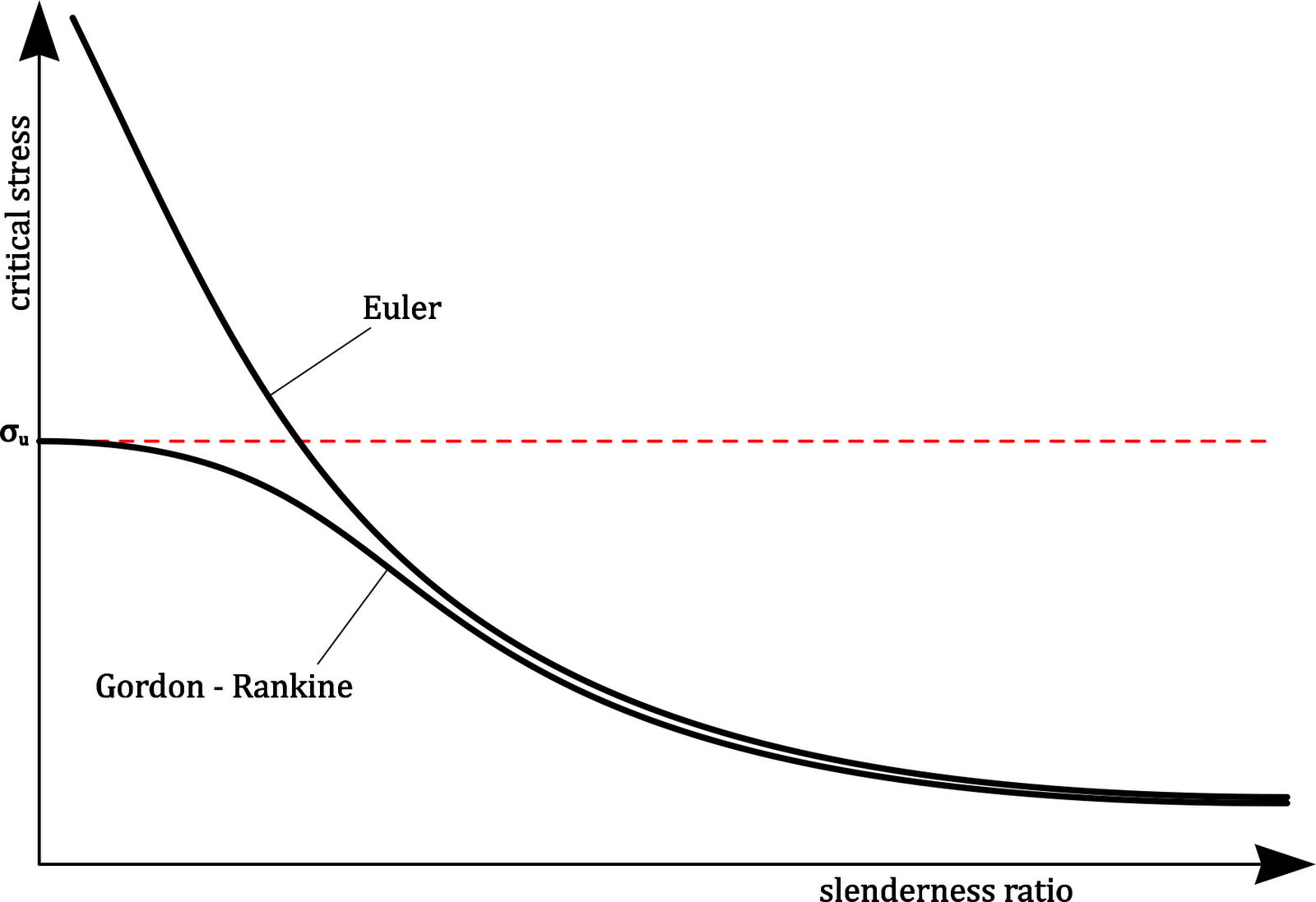
Figure 19 - Gordon - Rankine theory
|
On the left side of the graph, where the element is stocky, the critical stress is just the normal limit stress (in the case of this theory, it is the ultimate stress of the metal).
On the right side of the graph, where the element is very slender, the elastic Euler buckling behaviour controls and the yield of the material is not very relevant.
In between, the element will start to yield, across the section, before it can reach the full Euler load, and this causes additional deflections, which destabilise the element that much earlier.
Application of the various codes
Trust me, I am not going there. These codes are very complicated and it would take hundreds of pages to explain how any one of them works, and this guide is all about underlying behaviours, so that you can try to work out where the very odd equations are all coming from. The other purpose of the guide, and I really cannot stress this enough, is that if you can understand the qualitative behaviour, as opposed to an exact numerical analysis, then you will be able to get a feel for the trends and appreciate which parts of the problem are controlling, as well as those that your structure is not sensitive to.
If you want some worked examples, which demonstrate how some of the codes are applied, try looking at the Steel Construction Institute design guides from Steel-sci.com, or your favourite purveyor of electronic documents. They tend to cover the common structural types, which is eminently sensible, but they will give you a good stepping stone to go onto more complex scenarios.
Rant: one thing I will say is that I loathe the Eurocodes with a vengeance. Apart from the fact that their very rigour makes them impenetrable, until you have been working with them long enough to understand the subtleties of the subscripts (and bought a new pair of glasses to read them), they have done exactly what I have been warning my graduates not to do for many years. I have been offering severe retribution to any of my grads who refer to the slenderness charts as “Buckling curves” since they do not represent the point at which the member buckles, and it causes no end of confusion.And then the Eurocodes actually label the blasted charts as“Buckling curves”.
Aaaarrgghhhh !! (the author now goes off for a sulk in a darkened room with loud rock music at 100 watts per channel until his kids come down and demand “Daddy, turn your music down now, I can’t do my homework”). I have even started to talk about myself in the third person, which is never a good sign.
What the Eurocodes do explicitly, and what the other codes have been hiding from us all these years, is that slenderness, the value along the X-axis of the graphs, is not really a series of absolute values, but a measure of the local load at failure compared to the buckling load. For instance, if the axial yield load of your strut were 100kN, and the buckling load was 400kN, then you would have a normalised value of ¼, would be very near the Y-axis, and you would be able to design for a stress approaching yield. If, however, the axial yield load were 300kN, and the Euler buckling load was 100kN, then the strut would technically be described as wibbly wobbly and you would only be able to design for 10% of yield.
So to summarise, buckling is used in what the Eurocodes so annoyingly call the buckling curves, but the curves DO NOT represent the load at which the element will buckle.
Rant/sober warning: one of my major concerns with the Eurocodes is that they explicitly rely on calculating Euler or Eigenvalue buckling loads. I am a hard core engineer, and am very good at my job, with a large amount of experience: and that means that I am lucky if I get my structural model correct first time more than once in every ten structures – you can imagine the chance of success for a fresh grad. One of the things that makes me good at my job, apart from the people who have taken the time to tell me all the things that I am trying to tell you now, is that I know that I make mistakes. Typically, I will spend twice as much time vetting and tweaking a complex structural model as I took building it in the first place. There are a number of techniques that can be used for this, such as summing reactions, to check that they equal the total load input, and investigating the deflected shape to see that it makes sense. Unfortunately, Eigenvalue analysis is a black box: you put in the structure and a load, and then you get an answer of 2.63, and you cannot do the normal checks. Of course you can run the normal checks to see that it is behaving itself for the normal loads, but you cannot do the same thing for this piece of computer sleight of hand.
I have come across cases where engineers have re-assessed a structure using Eigenvalue and have increased the capacity from less than dead load to allow 40 tonne trucks over. Since the assessment code effectively uses a variation of eigenvalue, there should be no difference in the result, let alone a trebling of overall capacity. And eyebrows were not raised – scary.
There is talk of the British steel design community introducing BS5400 as a Non Contradictory Complementary Instruction to the Eurocode, so that it can be used in its place, and despite the known complexity of BS5400, it is less opaque than the Eurocode. Here endeth the rant for today.
Compact versus non compact and various other states
Fundamental: members can buckle locally in a section, as well as globally as a long member. These are two completely separate behaviours, but they do interact. The local buckling behaviour is dealt with by investigating the cross section, independent of the larger scale slenderness. This leads to cross sections being put into one of a number of separate classes, and these classes are treated in different ways. This is one of the few areas where I let my grads use the “B” word
The Eurocodes follow the old BS5950, using Classes 1 through 4, but does not, however, include the snappy BS5950 shorthand descriptions, which I have added for clarity. I will tend to follow the old BS5950 terminology even though my speciality is bridges. This is also quite ironic since my current role is assessment of complex bridges, and the assessment codes refer back to the now superseded British Standard BS5400 (in case you were wondering why I keep referring to an out of date code).
The four classes are (in order of reducing chunkiness – a good technical term):
Class 1 plastic: can form plastic hinges, including relatively large rotations
Class 2 compact: can reach full plastic moment without local buckling
Class 3 semi-compact: extreme compression fibre can reach design strength but full plastic moment cannot be reached
Class 4 slender: cross sections for which it is necessary to make allowance for local buckling.

Figure 20 - local buckling of compression flange which exceeds slenderness ratio
|

Figure 21- local buckling of square hollow section that exceeds slenderness ratio
|
BS5400 (and the assessment codes) splits steel sections into Compact and ones that are not compact (but let us call them Semi Compact for consistency). It does not concern itself with Class 1 sections since bridges are not usually designed using plastic collapse theory. It does not refer to slender sections (Class 4) directly: it does, however, allow a lower value of limiting stress to be used in place of the yield stress such that the outstand ratios are met and that is also the method used by the Network Rail assessment document.
Cross sections fall into the different classes depending on the ratios of critical dimensions to the local thickness, usually modified by the yield stress. A typical pair of checks come from BS5400 which has the following slenderness limits for a compression flange:
Compact: bfo/tfo < 12√(355/σy), and
Semi Compact: bfo/tfo < 14√(355/σy).
The checks only apply to parts of the cross section that are under compression since tension parts will tend to straighten out when stretched and obviously cannot buckle.
We have to be careful comparing the various construction types and codes because they all work in subtly different ways. For instance:- on riveted sections the Network Rail assessment code specifies the outstand from the notional edge of a rivet head, i.e. 0.8 x rivet diameter from the centre of the rivet.
- BS 5400 Part 3 would specify the same dimension to the centre of the bolts. It then specifies outstands from the toe of the root fillet of a rolled section but the supporting face (i.e. the edge of the web) for a welded section.
And now for the important bit, what we actually do with the different classes.
Plastic sections can be used in plastic mechanism analysis, where the various critical sections are allowed to form a series of plastic hinges.
Compact sections can go fully plastic over the full depth so the strain can go high enough to allow the entire section to go into either tensile or compressive yield. The capacity is then based on this plastic behaviour.
Semi Compact sections are allowed to yield at the extreme fibres in either tension or compression.
Aside: I have never seen why semi compact sections cannot go further into tensile yield if the section is unbalanced, but the rules only allow for the extreme tension fibre to go into yield and everything else stays elastic.
Slender sections are treated differently in the various codes.
BS5400 and the assessment code require the stress in the element to be kept to a value of limiting yield which would satisfy the normal slenderness limit. For instance, if the ratio were calculated at 21, but the limit was 14√(355/200) = 18.65 then the limiting stress would have to be reduced to 355(14/21)2 = 157.8 MPa, Notice that the limiting stress drops off very fast once the slenderness ratio is reached.
BS5950, the superseded building code, uses a much simpler method once the limits are exceeded. In simple terms, anything other than the material that meets certain criteria is ignored, hence if the outstand limit is 15ε and the actual is 18ε, then 3ε is ignored. For those of you without an eidetic memory, ε = √(275/py). Eurocodes use a similar method but, as usual, it is hard to decipher this, hence my use of an outdated code to make the point (you might find that this is one of my repeating themes).
Aside: I can understand where the code drafters were coming from because we were all taught at university something along the lines of “If a method of supporting a load can be found, then that is safe and it does not matter if we find the correct method”: I always forget whether that is a lower or upper bound theory, and to be quite honest I do not care. The theory may be fine when we are talking about adding an extra plate to a cross section, but in this case we could be talking about making a plate twice as wide as the slenderness limit and then ignoring the extra: the only problem that I see is that the extra width might cause the edge of the section to actually buckle at a very low level, and it will not just be the bit outside the limit that goes. If the tip of a flange outstand buckles, and becomes ineffective, then it could pull the rest of the flange with it and the entire thing fails. I am sure that greater minds than mine have looked into this, but I never feel happy with the method once we go too far beyond the limit.
There is one little subtlety that needs to be kept in mind, in case someone has either historically built, or wants to build, something that is not tightly fixed together. Figure 6 in BS5950 Part 3 demonstrates this very elegantly and is included below as Figure15. Yeah, yeah, I know that it is superseded but yaddah yaddah ….

Figure 22 - BS5950 Part 3 Figure 6
|
In the examples above, the strengthening plates are only fixed together by welds at the ends.
In the first part of a) the disturbing imperfection and force come from the tip of the original flange so the width is based on this original flange. But if this were to buckle upwards then the compound plate would just lift up in the middle because the welds are not stiff enough to make the two plates act compositely so the thickness is based on the original as well. In the second part of a) you get a similar stiffness from the separate plates, but the disturbing force is further out resulting in the larger width: this is possibly a little harsh, unless the compound plate is thicker than the original, but it is at least easy to apply.
In b) the compound plate could buckle upwards since there is no weld to hold it down in the middle: it is similar to one side of a square hollow section, but here the weld provides some fixity instead of the continuity around the section.
In c) the little stub outstand is being treated as though it were a flange in its own right, it is just measured from the flange instead of a web.You might get a similar situation on an historic bridge, if a series of plates were only joined together at the edges. The important point to consider is whether the plates are well fixed together, and therefore able to act as one stiff section, or if they are a series of plates that are just in close proximity but which will act independently.
One last recap to avoid confusion
There are two completely separate forms of buckling going on and they are acting in completely different directions: confusing the two directions is quite common, but can be easily avoided by considering where the relevant bit of steel is trying to move.
 |
Things can fall apart in many ways
Some people design or assess a structure by making the elements strong enough to resist the applied forces and moments. The problem with that is that you have to get everything right and it is very easy to miss something. But there is another way of looking at structures which often picks up problems, and that is to look at how the structure can fail, and then to design to prevent this.
The structure below is a typical railway truss, with a top chord under compression, and therefore prone to large scale instability. The top chord is the part of the structure that most people instinctively home in on, for instability 1, and the behaviour is investigated either for plan cross bracing or for U-frame behaviour (some other time …), or sometimes with no bracing at all.
Figure 24 - various modes of instability
|
But there are a number of other potential instabilities, all with their own effective lengths and stiffnesses. Unfortunately it is very hard to draw three-dimensional deflections on a two dimensional piece of paper, so hopefully you will be able to understand which directions I am talking about.
Number 2 is movement in the plane of the truss. It is unlikely as drawn, since the truss is deep in that direction and therefore stiff. If there were no bracing members in the little sub truss then it would be different.Number 3 is in the same direction, but is moving between the panel points.
Number 4 is where the little sub truss members are in compression and are able to move in the plane of the truss. As drawn, this mode is unlikely because …
Number 5 would have the same force and effective length but the plate is less stiff in a direction perpendicular to the sub frame.
Number 6, where the truss is shown in elevation, has the entire sub truss deflecting perpendicular to that truss, and finally …
Number 7 is where two sub trusses are crossing over but are pinned in the middle: in this case the instability has two half waves.So as you can see, all the little possibilities have to be considered. As I said, it is important to understand how things can fail and do the math to suit.
Another last bit to cause confusion
This is getting very much like the Hitch Hikers Guide to the Galaxy trilogy, which is now up to six parts: you read the last recap and then another bit arrives.
Figure 37 in BS5400 is the slenderness graph for struts. The equivalent graph for beams is Figure 11. The graph has a very similar form to the strut graph, with the critical limit dropping off with increasing slenderness. Rather than reducing the limiting compressive stress, the moment is limited instead. Although I can understand this with a non-compact beam, i.e. it remains elastic under design load, I cannot get my head around how this can be considered with plastic behaviour. The basis of the slenderness argument is, as discussed before, that the axial stress is limited so that the total of the axial and induced bending stress is limited to yield. But if the graph limits us to, say, 60% of yield, this means that the stress in the top flange would be varying from 20 to 100% of yield. And yet for the relevant section modulus to be plastic, with the web fully yielded, the entire flange has to go plastic, and that is clearly not happening.
And the moral of this story is that even with many decades of experience, a lot of research and a number of colleagues/mentors who took the time to teach me, no-one knows everything, and if you have a nice simple explanation for me, I would be much obliged for some hints.
TO BE CONTINUED …
Apparently, following the blog might tell you when I add new sections, which happens every few weeks at the moment. Comments can also be helpful (preferably polite) since everything that I write is perfectly clear to me, but that does not mean that it is actually clear.
Explained very lucidly...waiting for your blog on U frame behaviour
ReplyDeleteIt took a while, but I got there with a U frame section eventually. It was nasty and I learnt a lot of things along the way. Thnaks for the interest and good suggestion
DeleteThank you Adrian !
Delete